renue Inc. (Headquarters: Minato-ku, Tokyo; CEO: Yusuke Yamamoto; hereinafter 'renue') announces the launch of a new 'Movable Assembly' feature for Drawing Agent, its AI that automatically generates 3D models from technical drawings. This new functionality reads joints from assembly drawings and generates 3D models with movable articulations.
The generated models are automatically verified by AI through motion simulation, and users can also interactively manipulate joints on-screen to confirm movement.
Overview of the 'Movable Assembly' Feature
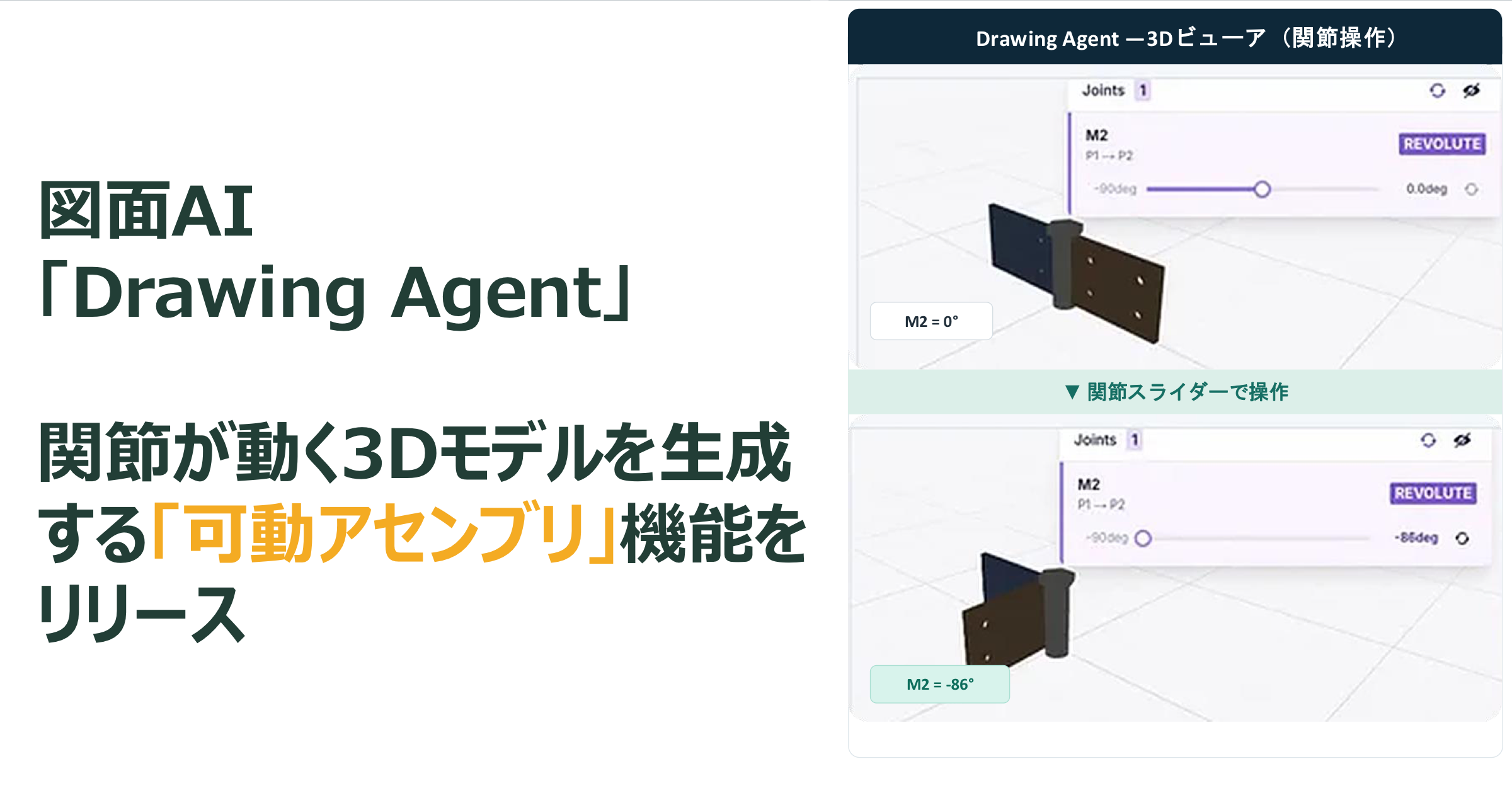
Drawing Agent now includes a new 'Movable Assembly' feature that interprets 'motion' information from assembly drawings and generates 3D models with functional joints. Simply upload a 2D drawing to instantly receive a ready-to-animate 3D model.
Taking a hinge assembly drawing as an example, the system separates two plates and a hinge pin into individual components, and interprets rotational joints and motion ranges from rotation arrows or joint tables. The generated 3D model can be opened and closed within the detected range using an on-screen slider. The feature supports both rotational and linear joints, and can handle mechanisms with multiple interconnected joints.
The process doesn't end at generation. The AI automatically moves joints to sample poses to verify that connected parts do not detach during motion. Models that fail verification are not finalized, and unverified items are explicitly marked as 'Unverified'.
Models with motion data can be exported in URDF (used in robotics development) and MJCF (used in physics simulation) formats, including mass, center of gravity, inertia tensor, and joint motion limits.
Detected joints can be reviewed and corrected on-screen before model generation, based on a design principle that allows human final confirmation of AI interpretations. No special setup is required—users can access the service directly via browser by uploading drawings.
This expands 2D drawing digitization from static shape reproduction to full dynamic mechanism simulation.
About Drawing Agent
Drawing Agent is an AI-powered drawing-to-3D tool that automatically generates 3D CAD models (STEP/GLB/STL) by analyzing uploaded 2D drawings (images, PDF, DXF/DWG). It enables designers without CAD software expertise to convert drawings into 3D data.
Since its public release in March 2026, the platform has enhanced its capabilities with features such as pre-referencing of part information, drawing cleanup, automatic tool selection by AI agents, material- and part-based decomposition, multi-part assembly, and structural analysis (CAE functionality, beta).
Previous release: https://prtimes.jp/main/html/rd/p/000000041.000091210.html
Development Background and Objectives
Manufacturing and construction industries possess vast archives of legacy 2D drawings. The demand to use these drawings as 3D data—for quoting, production planning, interference checks, mechanism validation, and digital twin creation—is growing. As robotics and physical simulation become more widespread, the cost of preparing 'animatable 3D data' has emerged as a new bottleneck.
The assembly feature added in May automated part placement and interference checking. The new 'Movable Assembly' feature builds on this foundation by adding a 'motion' layer.
However, previous 3D conversion methods had limitations. Assembly drawings contain not only part shapes but also mechanism information—'where', 'around which axis', and 'how far' parts move. Rotation arrows, hinge configurations, and joint table entries (joint type, axis, range) are typical examples. Traditional automated 3D conversion focused on shape reproduction, leaving motion data untransferred to 3D models.
Hinges are a typical case. Even with a simple structure of two plates and one pin, losing the 'plate rotates around the pin' relationship results in a single solid model of three metal parts. To analyze it as a mechanism, users had to manually split parts and redefine joints in CAD software.
Hinges are the smallest movable mechanisms found in doors, enclosures, jigs, and equipment covers—ubiquitous across industries. Even this basic mechanism lost its 'opening/closing' essence in traditional 3D conversion.
The goal of the Movable Assembly feature is to digitize motion information from drawings into 3D data. The answers are already in the drawings—the key is to fully interpret them. The system extracts joint types, rotation axes, and motion ranges alongside part shapes and dimensions, delivering models that are ready to move upon receipt.
Additionally, to ensure human trust in AI-generated mechanisms, motion verification is automated. The aim is not to accept AI output based on appearance alone, but to deliver results that have been tested through motion simulation.
Target applications include initial mechanism validation in design departments, motion verification of jigs and equipment in manufacturing engineering, and animated explanations in sales or educational materials—any scenario requiring 'moving models'.
Previous Challenges
Loss of 'Motion' in 3D Models
Rotation arrows and motion range annotations in assembly drawings are instantly understandable to humans. However, traditional drawing-to-3D conversion prioritized shape, treating these as secondary notes. Even when a joint table clearly states 'Rotation, Z-axis, Range: -90° to +90°', the output 3D model remains a single rigid body with all parts fixed.
Mechanism information present in drawings was lost during 3D conversion.
Converting a hinge drawing into a 3D model that cannot open or close renders it useless for evaluating mounting positions or opening angles. Even with accurate shapes, the 3D data fails to meet its intended purpose. Users end up returning to the original drawing to verify motion.
Movable Part Definition Required Manual Re-work
For mechanism analysis or simulation, models must be split into links, and joint parent-child relationships, rotation axes, and motion ranges must be redefined in software. For URDF files used in robot simulation, mass, center of gravity, and inertia per link must also be set. Despite the information being already in the drawing, users had to re-enter the same data manually.
This task scales with the number of parts and joints. Even if 3D conversion is automated, as long as joint definition remains manual, the time to mechanism validation cannot be reduced.
Models That 'Should Move' Don't
AI-generated assembly models may appear correct visually but suffer from misaligned rotation centers, separated parts, or joints detaching when animated. Even a slight offset in the rotation axis can invalidate the mechanism.
Generative AI often presents incorrect results with high confidence, making such defects hard to detect through visual inspection of static images.
Manually verifying motion for each joint would offset time saved by automation with increased review effort. If defects are discovered late in the process, rework costs escalate significantly.
Key Features of 'Movable Assembly'
The Movable Assembly feature consists of three stages: interpretation, interaction, and verification.
FACT BOX
- Source: PR TIMES
- Category: New Product
- Products / services: Drawing Agent